"The conundrum forcing many
Material Handling Equipment (MHE) manufacturers today to scratch their heads is
“How do I make my product simple, yet elegant?” The seemingly uncomplicated
task of lifting and lowering stacker and scissor lift platforms has driven
designers over the edge in the quest for a compact and clever hydraulic system
that fits the bill."
A few Western and Japanese multinational hydraulic valve manufacturing companies were producing a CETOP subplate-mounted modular stack on which was a Relief Valve, Pilot Operated Check valve and a double solenoid directional valve with a Throttle Valve thrown in for good measure (Figure 1).
Switching on the pump meant it went directly into the ‘On Load’ condition with the pressure ramping up suddenly. When the Solenoid S1 was energized, the load was lifted. In the neutral position, the load was successfully held in position and when the Solenoid S2 was energized, the load lowered.
One of the fundamental problems, out of the many, of this system
was that pump was “On Load” when started. The other was that when the load was
lowered, the pump was on full load as determined by the pressure setting on the
Relief Valve. Also, the modular design of the system consequently meant that
there had to be long piping between the modular stack and the cylinder. Hence
there was a chance of hose burst and collapse of the load if an efficient hose
burst valve/velocity fuse was not in place.
These problems ultimately gave rise to:
1. Higher power consumption
2. Higher system noise
3. Higher heating of the oil
4. Unpredictable safety
These problems ultimately gave rise to:
1. Higher power consumption
2. Higher system noise
3. Higher heating of the oil
4. Unpredictable safety
All put together the system
was inefficient but it worked and did the job that it ought to have done.
Customers opted for the same, not out of choice, but because there was not much
else available in the market. The companies which sold the system had little or
no concept and there was no enthusiasm to leave their comfort zone and offer
something better. Some of the Italian cartridge valve manufacturers had this
system but India
Quest
for the “Simple Solution”
 |
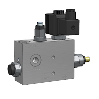
| Figure 2: The Lift - Lower Block from Tucson |
Approximately fifteen years ago,
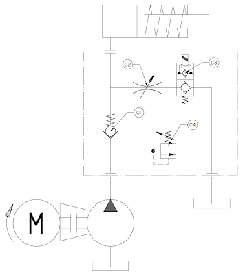
The system was an integration of a Check, a Solenoid, a Throttle and a Relief Valve into one compact manifold body. The block could be mounted directly at the base of the actuator with rigid piping between the two. Simple and clearly marked porting (Pump, Cylinder and Tank) prevented unnecessary confusion and excess piping and gave a clean look to the equipment.
Over the years, the product grew in popularity,
chiefly by word of mouth, and the system that was introduced then, functionally
still remains the same albeit with a few changes due to the leaps in cartridge
valve technology. The system essentially works with a single acting cylinder
and can be used in scissor lifts, platform stackers and clamping blocks.
 |
Figure
2: The Lift-Lower block has a
simple yet effective design without a lot of confusing porting allowing for easy installation and servicing. One Inlet (Pressure) Port and two Outlet (System and Tank) Ports make piping
simple.
|
Multiple Actuators
 |
| Figure 4: Multiple Lift Lower blocks can be connected in parallel to control more than one actuator as in the case of car parks. One relief valve will suffice for ‘n’ number of systems. The actuators can only be raised one at a time; however, they can all be brought down together. |
The design, in hindsight, seems oddly simple,
covering all the issues plaguing its modular predecessor. However, what happens
when there is more than one actuator to be controlled as in the case of car
parks? Since the lifting of the actuator is dependant on the pump being on,
does this imply that there will be one dedicated pump for each cylinder? The
answer is No!
It is indeed is possible to have one power pack
supporting many actuators operating many lifts. With each actuator having its
own independent control valve for lifting and capable of being disengaged from
the main pump for lowering. The valves are simply modified as shown in Figure 4.
Here the use of a bidirectional Poppet Valve
in place of the check valve allows the isolation of each actuator allowing only
one cylinder to be lifted at one time. The lowering, however, can be
simultaneous. The standard cavity allows for free switching of the cartridges
making the design simpler to implement.
Since there is a parallel attachment of the
systems, a pressure spike in any actuator will be sensed in all of them. This
enables the customer to use only one relief valve for the entire system.
High Speed Lowering
 |
| Figure 5: High Speed Lowering |
Sometimes loads also have to be lowered at
very high speeds as in the case of dam gates. For cases such as this, an
additional Pilot Operated Check valve with a three port, two position Directional
Control valve is needed as show in Figure 5. The modification increases the cost of the system
but is excellent for rapid lowering of the cylinder in places such as Dam Gates
While the pump is sized for a flow of around
50 lpm the PO check valves are sized for flows
as high as 300 lpm. The directional control valve enables the selection of the
pilot line. Normally, the pilot pressure comes from the tank line which ensures
that the check valve remains firmly seated. When the solenoid is energized, the
pilot pressure is sensed from the cylinder pressure line. The pilot ratio
(difference in area between the pilot section and pressure section) of the
Pilot Check opens the check valve dumping the oil at up to 300 lpm.
Salient
Features
 |
| Lift Lower System - 50 lpm |
The system can actually be mounted in close
proximity to cylinder with rigid pipe connection making use of the hose burst
valve redundant. The system also comes with a manual over ride for the solenoids
which can be used in case of a power failure. Solenoid voltages come in
different variants such as 24VDC, 12VDC or 230VAC. DC voltages are preferred as
the coils last longer and give a trouble free life free of maintenance. The
hydraulic systems are available in either 25 lpm or for 50 lpm capacities.
Poppet valves are adequately over sized so that loads can be lowered even if
the weight is low. Tucson Hydrocontrols uses the entire set of valves of its
own design and manufacture except the poppet valves. The block is manufactured
out of aluminum which keeps the weight down to a minimum.
So in retrospect, we can see that the system provides exactly what is
required by the industry today. With simple modifications it can suit a wide
range of applications depending on the customer’s requirements.
For more information:


Good study of scissor lift and good learn information from this post keep posting more and thanks for post..
ReplyDeleteNice post about Hydraulic Scissors Lift. Thanks for sharing the valid information. We are also Manufacturers and Supplier of Hydraulic Scissors Lift in India
ReplyDeleteHey.Was just surfing about Hydraulic Scissors Lift and got to see your blog post.Going through your blog post makes me understand better about Hydraulic Scissors Lift.
ReplyDeleteI was just surfing through Hydraulic Scissor lifts suppliers and manufacturers in Delhi and found your blog post interesting.Thanks for sharing.
ReplyDeleteMy friend is starting work in construction. I know that he is going to be using some new equipment. He will definitely need to know the details of using a scissor lift. I want him to make sure he will be safe while using it as well. http://www.skyriderequipment.com
ReplyDeleteWhen buying scissor lifts tables you should first take into consideration the amount of deflection that your application can tolerate. It is good to have a machine that is as precise as possible, but the only drawback is that the more precise the machine is the more it is going to cost you.
ReplyDeleteGreat write up! It will definitely be very helpful for people to understand types of Hydraulic Scissor Lifts.
ReplyDeleteHey thanks for sharing this article. It helps to understand about hydraulic scissor lift.
ReplyDelete