Tuesday, January 31, 2012

Technical Article - Stackers and Scissor Lifts Systems


"The conundrum forcing many Material Handling Equipment (MHE) manufacturers today to scratch their heads is “How do I make my product simple, yet elegant?” The seemingly uncomplicated task of lifting and lowering stacker and scissor lift platforms has driven designers over the edge in the quest for a compact and clever hydraulic system that fits the bill."


A few Western and Japanese multinational hydraulic valve manufacturing companies were producing a CETOP subplate-mounted modular stack on which was a Relief Valve, Pilot Operated Check valve and a double solenoid directional valve with a Throttle Valve thrown in for good measure (Figure 1).
Out-dated system for scissor lifts
Figure 1: Previously, CETOP subplate
mounted modular stacks of Directional 
Control, Pilot Check and Flow Control
valves provided control of the cylinder
which gave rise to more than a few
complications for the customer.

Switching on the pump meant it went directly into the ‘On Load’ condition with the pressure ramping up suddenly. When the Solenoid S1 was energized, the load was lifted. In the neutral position, the load was successfully held in position and when the Solenoid S2 was energized, the load lowered.

One of the fundamental problems, out of the many, of this system was that pump was “On Load” when started. The other was that when the load was lowered, the pump was on full load as determined by the pressure setting on the Relief Valve. Also, the modular design of the system consequently meant that there had to be long piping between the modular stack and the cylinder. Hence there was a chance of hose burst and collapse of the load if an efficient hose burst valve/velocity fuse was not in place.

These problems ultimately gave rise to:
1. Higher power consumption
2. Higher system noise
3. Higher heating of the oil
4. Unpredictable safety

All put together the system was inefficient but it worked and did the job that it ought to have done. Customers opted for the same, not out of choice, but because there was not much else available in the market. The companies which sold the system had little or no concept and there was no enthusiasm to leave their comfort zone and offer something better. Some of the Italian cartridge valve manufacturers had this system but India was not keen to adopt it. “Why Change?” is the question often customers asked and moved on.

Quest for the “Simple Solution”
Lift Lower Block from Tucson
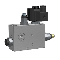
Figure 2: The Lift - Lower Block from Tucson

Approximately fifteen years ago, Tucson introduced their first “Lift-Lower Block” (Figure 2). Needless to say, as with any new technology, the product was a monumental failure. Not because it was functionally flawed, but because companies did not have the mindset to change to something different. 
The system was an integration of a Check, a Solenoid, a Throttle and a Relief Valve into one compact manifold body. The block could be mounted directly at the base of the actuator with rigid piping between the two. Simple and clearly marked porting (Pump, Cylinder and Tank) prevented unnecessary confusion and excess piping and gave a clean look to the equipment.

Over the years, the product grew in popularity, chiefly by word of mouth, and the system that was introduced then, functionally still remains the same albeit with a few changes due to the leaps in cartridge valve technology. The system essentially works with a single acting cylinder and can be used in scissor lifts, platform stackers and clamping blocks.
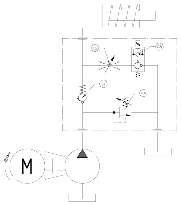
Tucson Lift Lower Valve Schematic
Figure 2: The Lift-Lower block has a simple yet effective design without a lot of confusing porting  allowing for easy installation and servicing. One Inlet (Pressure) Port and two Outlet (System and Tank) Ports make piping simple.
As shown in Figure 3, when the pump is switched on, the load is lifted by the pump pressure as the oil flows over the Check Valve (C1). When the desired extension of the cylinder is reached, the pump is switched of and the load stays in position as the oil and hence the cylinder is locked in place by the Check Valve  and the poppet type Solenoid Valve (C3). If the cylinder should happen to reach the end of the stroke, the pump blows over the Relief Valve (C4) keeping the system safe. When the load is to be lowered, pump remains in the switched off position and Solenoid Valve is switched on. Oil finds passage through the Throttle Valve (C2) and through the now open Solenoid Valve to tank. Rate of lowering is determined by the opening of Throttle Valve.


Multiple Actuators

Tucson Lift Lower Valves in Series
Figure 4: Multiple Lift Lower blocks can be connected in parallel to control more than one actuator as in the case of car parks. One relief valve will suffice for ‘n’ number of systems. The actuators can only be raised one at a time; however, they can all be brought down together.

The design, in hindsight, seems oddly simple, covering all the issues plaguing its modular predecessor. However, what happens when there is more than one actuator to be controlled as in the case of car parks? Since the lifting of the actuator is dependant on the pump being on, does this imply that there will be one dedicated pump for each cylinder? The answer is No!
It is indeed is possible to have one power pack supporting many actuators operating many lifts. With each actuator having its own independent control valve for lifting and capable of being disengaged from the main pump for lowering. The valves are simply modified as shown in Figure 4.

Here the use of a bidirectional Poppet Valve in place of the check valve allows the isolation of each actuator allowing only one cylinder to be lifted at one time. The lowering, however, can be simultaneous. The standard cavity allows for free switching of the cartridges making the design simpler to implement.

Since there is a parallel attachment of the systems, a pressure spike in any actuator will be sensed in all of them. This enables the customer to use only one relief valve for the entire system.

High Speed Lowering
Tucson Lift Lower Valve with High Speed Lowering
Figure 5: High Speed Lowering

Sometimes loads also have to be lowered at very high speeds as in the case of dam gates. For cases such as this, an additional Pilot Operated Check valve with a three port, two position Directional Control valve is needed as show in Figure 5. The modification increases the cost of the system but is excellent for rapid lowering of the cylinder in places such as Dam Gates.

While the pump is sized for a flow of around 50 lpm the PO check valves are sized for flows as high as 300 lpm. The directional control valve enables the selection of the pilot line. Normally, the pilot pressure comes from the tank line which ensures that the check valve remains firmly seated. When the solenoid is energized, the pilot pressure is sensed from the cylinder pressure line. The pilot ratio (difference in area between the pilot section and pressure section) of the Pilot Check opens the check valve dumping the oil at up to 300 lpm.

Salient Features
LLB50
Lift Lower System - 50 lpm
The system can actually be mounted in close proximity to cylinder with rigid pipe connection making use of the hose burst valve redundant. The system also comes with a manual over ride for the solenoids which can be used in case of a power failure. Solenoid voltages come in different variants such as 24VDC, 12VDC or 230VAC. DC voltages are preferred as the coils last longer and give a trouble free life free of maintenance. The hydraulic systems are available in either 25 lpm or for 50 lpm capacities. Poppet valves are adequately over sized so that loads can be lowered even if the weight is low. Tucson Hydrocontrols uses the entire set of valves of its own design and manufacture except the poppet valves. The block is manufactured out of aluminum which keeps the weight down to a minimum.

So in retrospect, we can see that the system provides exactly what is required by the industry today. With simple modifications it can suit a wide range of applications depending on the customer’s requirements.


For more information:


Saturday, January 21, 2012

Overcentre Valves and Counterbalance Valves


Application
Overcentre valves give static and dynamic control of loads by regulating flow into and out of hydraulic actuators. The Overcentre valve will stop the load from running away in the event of a hose burst. If open centre directional control valves are used, they will allow the thermal expansion relief of the hydraulic fluid. These valves provide excellent hose burst protection.

Operation
The check section allows free flow into the actuator (from 2 to 1) then holds and locks the load against movement (from 1 to 2). The pilot pressure in the pilot port (3) will give a controlled movement to piston when the pressure is applied. 

The pressure required to open the valve and allow movement depends on the pilot ratio of the valve. For optimization of load control and energy usage, a choice of pilot ratios can be made available. 

The pressure required to open the valve and start actuator movement can be calculated as follows:

Pilot Pressure = (Relief Setting - Load Pressure) / Pilot Ratio


Pilot Ratios

3:1 
Best suited for extremely unstable applications such as long booms


4:1 Best suited for applications with variable  load and unstable 
machine structure
5:1 Best suited for applications with variable  load and unstable 
machine structure

7:1 Best suited for applications where the load remains relatively constant


Specifications


Max Flow
Up to 400 litres/min
Max. Load Induced Pressure
270 bar
Relief Setting
350 bar
Cartridge Material
Working Parts: Hardened and Ground External Surfaces: Zinc Plated
Operating Temperature
-20’C to +90’C
Port Sizes
3/8” BSP to 1.1/4” BSP
Leakage
Less than 35 millilitres/min

Monday, January 9, 2012

The most important component of every hydraulic system. Hydraulic Oil

Here's four quick tips for you to get the most out of THE most important component of every hydraulic system  - the oil:


1. Don't change the oil - filter it.

Water or particle contamination rarely necessitates an oil change - unless the contamination has resulted in additive depletion or base oil degradation. These contaminants can be removed from hydraulic fluid by filtration. 

2. Eliminate particle contamination to reduce breakdowns...
Research has shown that maintaining fluid cleanliness at ISO 4406 16/14/11 will result in a tenfold increase in the average time between breakdowns when compared with a fluid cleanliness level of 24/22/19. This is based on the findings of a three-year study of 117 mobile and industrial hydraulic machines to determine the correlation between fluid cleanliness and breakdown frequency. 

3. ...and extend fluid life.
Particle contamination reduces the service life of hydraulic oil by stripping additives and promoting oxidation. Additives attach to particles, which are then removed by the filters or settle to the bottom of the reservoir. Wear metal caused by particle abrasion is a catalyst for fluid oxidation. 

4. Keep it cool.
Elevated operating temperatures increase the rate at which the oil oxidizes and this decreases its service life. By-products of the oil oxidation process - varnish and sludge, can cause reliability issues such as valve spool stiction and filter clogging.
Dirty Oil with O-ring bits and metal scrap


From the above, we can see that control contamination forms an integral part of how well your system works. Studies have shown that it costs 10 times more to extract contaminants from hydraulic fluid than it does to exclude them in the first place.


Three common points of contaminant ingression are:

1. Reservoir breather.
Standard filler-cap breathers fitted to the majority of hydraulic reservoirs are not effective in preventing ingression of airborne contaminants. All air entering the reservoir should be adequately filtered. In damp environments (e.g. marine applications, tropical
climates) desiccant breathers are essential to prevent the ingression of airborne moisture. 

2. Cylinders.
Worn or damaged rod-wiper seals and pitted or gouged cylinder rods give dust and other contaminants an easy path into the system. 
Fitting rod protectors (bellows) to cylinders operating in abrasive or corrosive environments can extend rod and wiper seal life and provides an extra barrier to the ingression of contaminants via the cylinder rod. 

3. Plumbing.
Where fluid leaks out, contamination can get in. The immediate rectification of hydraulic system leaks not only minimizes the cost of clean-up, disposal and replacement fluid, it also saves the hidden cost of removing ingested contaminants.  


Now this may spur you to believe that the best solution for maintiaing cleanliness in your system is to simply replace the oil. "New hydraulic oil is clean hydraulic oil".

THIS IS A MYTH!

New hydraulic oil straight from the drum, has a typical cleanliness level of ISO 4406 23/21/18.

Now that number may not mean a lot to you, but it's four cleanliness code levels below that considered ideal for a high pressure, high performance hydraulic system.

Looking at it another way, a 100 lpm pump operating continuously in hydraulic oil at 23/21/18 will circulate 1,600 kilograms of dirt to the hydraulic system's components each year!!! That's approximately the weight of two Hyundai Santros

To add hydraulic oil, and not the dirt, always filter new oil prior to use in a hydraulic system.

This can be accomplished by pumping the oil into the hydraulic reservoir through the system's return filter. The easiest way to do this is to install a tee in the return line and attach a quick-connector to the branch of this tee. Attach the other half of the quick-connector to the discharge hose of a drum pump. When hydraulic oil needs to be added to the reservoir, the drum pump is coupled to the return line and the oil is pumped into the reservoir through the return filter. As well as filtering the oil, spills are avoided and the ingress of external contamination is prevented.


-Excerpts from Brendan Casey, Author of 'Insider Secrets to Hydraulics'

For more articles on Hydraulics, visit Tucson Hydrocontrols - Downloads