 |
| Deciding between a loud system and a leaky one when decompression is involved need not be as hard as you think.
|
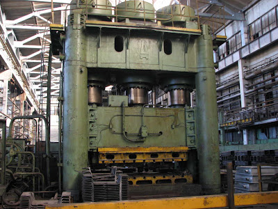
A lot of the time, we get
complaints from press manufacturers that come to us with the following problem:
"I have a cylinder on my
press and every time I have to unload it, there is a loud banging sound."
If we consider that all the
other mechanical parts of the press are working fine (i.e. the problem lies
with the hydraulics), it is most likely caused by the uncontrolled decompression
of the hydraulic fluid. The problem arises because hydraulic fluid is not
perfectly rigid.
One of the popular
misconceptions with hydraulics today is that fluids are incompressible within
systems. The fact is that they are compressible, albeit the compressibility is
not as large as in the case of gasses. The ratio of a fluid's decrease in
volume as a result of increase in pressure is given by its bulk modulus of
elasticity. The bulk modulus for most hydraulic fluids is approximately 17,000
kg/cm2 which results in a volume change of around 0.4% per 70 bar (1000 psi).
When the change in volume exceeds 160 cc, decompression must be controlled.
The compression of hydraulic
fluid results in storage of energy, similar to the potential energy stored in a
compressed spring. Like a compressed spring, compressed fluid has the ability
to do work. If decompression is not controlled, the stored energy dissipates
instantaneously. This sudden release of energy accelerates the fluid, which
does work on anything in its path. Uncontrolled decompression stresses
hydraulic hoses, pipes and fittings, creates noise and can cause pressure
transients that damage hydraulic components. This is similar to a balloon burst
by means of a pin when the compressed air is opened to atmosphere rather than
allowing the air to be let out smoothly.
 |
Figure 1:Successive
loading of a cylinder leads
to a pressure rise
in the fluid contained within. |
Consider a system as shown in Figure 1 below. The cylinder bore is 100 cm² and the height is 10 cm.If we load the cylinder with a 7000 Kg weight the height which was 10 cm initially will now become 9.9 cm. Thus there is a volume reduction of 1% (or 10cc). Here an assumption is made that the system is not perfectly rigid i.e. cylinder diameter does change. Add another 7000 Kg and the height will reduce to 9.81 cm, and another 7000 Kg would make it approx 9.712 cm and so on. Thus increase in weight would reduce the volume.
Similarly if we started with 21000 kg of weight on a closed cylinder with 100cm sq area and 10 cm height, and we remove 7000 Kg weight, the height would increase to 10.1 cm. remove another 7000 Kg and the height would be about 10.2, remove another 7000 Kg and the height would be about 10.3 cm.
Note: The relationship between the pressure and the volume is not linear here but exponential. Adding 7000 bar of pressure will not compress the fluid to zero volume.
 |
Figure 2: An enclosed fluid being pressurised
will
develop potential energy similar to that of a compressed
spring. This
energy is then released instantaneously as
noise and vibrations when the fluid
is decompressed
|
Now we take another example
shown in Figure 2 below. We have an enclosed chamber of volume 100 cc in which
a pump is pumping oil. The Relief Valve is set at 350
bar and as soon as the pressure in the system reaches 350 bar, we would find
the pump blowing over the Relief valve. If the pump is shut off, the Check
valve will hold the pressure in the tank at 350 bar. In order to lower the
pressure all that is needed to be done is to open the Shut Off valve. How much
oil should come out of this valve? If we remove 1cc of oil, the pressure would
drop to 280 bar; another removal of approx 1cc would bring it to 210 bar;
another removal of approx 3cc will bring it to zero pressure. This phenomenon
is what is used in decompression circuits.
The fluid needs to be removed
gradually. If the shut off valve is opened suddenly, the fluid will be exposed
to atmospheric pressure and approx 5cc of oil (the amount required to bring the
oil to atmospheric pressure) will escape making a big noise and the chatter of
system.
There are two popular methods used to achieve decompression of a
circuit.
1. Using a Pilot Operated Check valve with an inbuilt decompression
feature (Figure 3).
2. Using a poppet type decompression valve for allowing few ccs
of oil to escape followed by the main opening of the pilot check valve holding
the load in place
 |
| Figure 3: Pilot Check Valves with in-built decompression feature. |
 |
Figure 4: Decompression
using PO Check with
internal decompression
feature |
Use of a Pilot Operated Check
valve with decompression feature has its advantages. It gives a compact system
and a cheap one (Figure 4). However, the decompression feature in a Pilot
Operated check valve increases the area ratio of the valve. A standard Pilot
Check valve has an area ratio between 3 and 4 (5 in extreme cases). Thus a 300
bar system will open between 75-100 bar. Use of the decompression type Pilot
Check valve increases the area ratio to about 20 (25 in some cases). Therefore
a 300 bar system fitted with Decompression Pilot Check with area ratio of 25
will open at 12 bar and that with area ratio of 20 will open at 15 bar. This
will reduce the loud bang in the system which occurs when an un-decompressed
Pilot Check valve opens and the system will become smoother. This looks
perfectly fine and is acceptable to customers.
Now take the same system when
it is set to 100 bar (as in the case of many pressing applications). The same
decompression type Pilot Check valve (with area ratio between 20 to 25) will
open the valve between 4-5 bar. The standard pressure drop across a moderately
clogged filter is 2 bar which an excessively clogged filter may issue pressure
drops of even 4 bar.
This is notwithstanding the various other pressure drops
caused due to hydraulic fittings such as elbows, contaminants in the pipe
and/or other unwanted resistances to flow in the tank line. Thus one tends to
think that there is some problem with Pilot Check valve, ignoring the fact that
the problem lies with the circuit design. These systems will work only when the
system pressure is always 250 bar+.
 |
| Figure 5: Isolated
Holding and Decompressing circuits |
The solution to the above
problem is to isolate the Decompression system from the Pilot Check system
using a solenoid valve as shown in Figure 5. Along with the solenoid valve, an
orifice of size 0.8 to 1.6 mm is used as well. The potential energy of the
compressed fluid is converted into heat by metering the compressed volume of
fluid across the orifice. The solenoid valve is a poppet type valve with metal
on metal contacts that ensure that the valve has zero leakages. The valve opens
before the main stage DC valve and releases a few drops of oil. This ensures
that the cylinder pressure is near zero when the main solenoid valve opens.
This allows the Pilot Operated Check (with standard pilot ratios from 3 to 4)
to operate without any noise or vibration problems. This system, albeit costly,
works well through all pressure ranges; whether in a high pressure system of
300 bar or a low pressure one of 100 bar.
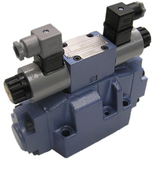
Tucson offers various types of decompression solenoids in
either a line mounting or a subplate mounting. Tucson
recommends a DC solenoid as this has a longer life over its AC counterpart.
This is due to the rectifier plug embedded on the solenoid coil could get
damaged if there is a voltage spike. The solenoids in Tucson
are offered in 12V and 24V DC and 230V AC. Many major press manufacturing units
have changed over from a decompression Pilot Check Valve to multi stage
Solenoid Decompression valves, which are only a shade more expensive but
reliable, accurate and long lasting.


